About:
As mentioned erlier, Pi switch is basically a "switch" you can turn on from anywhere in world where you have internet access.
It uses Raspberry pi and external circuit ,which of you can find schematics,but also the board on my
Github page.
Pi Switch was invented as a solution to a problem, I needed to turn on my servers from anywhere i wanted to!
Principle:
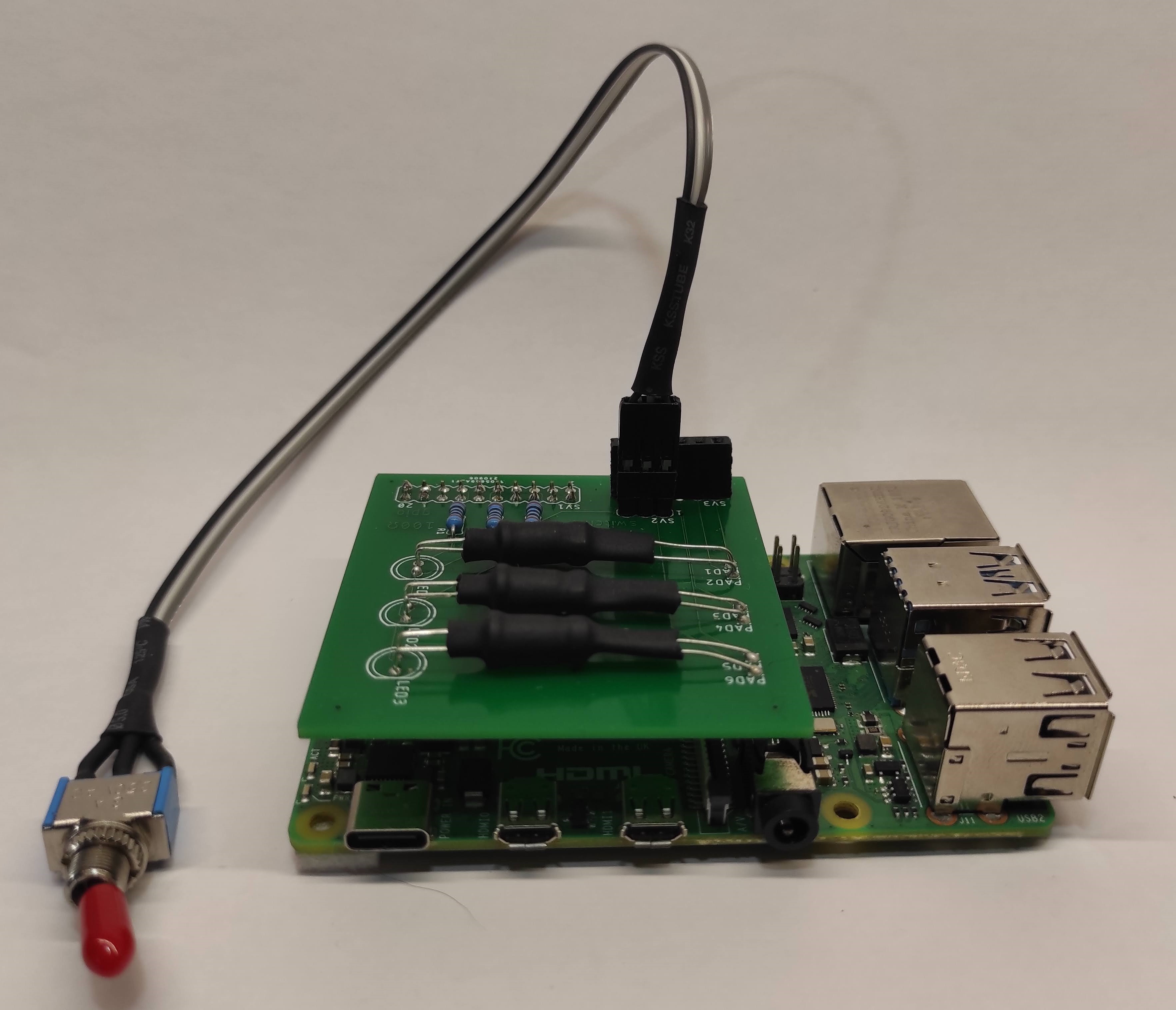
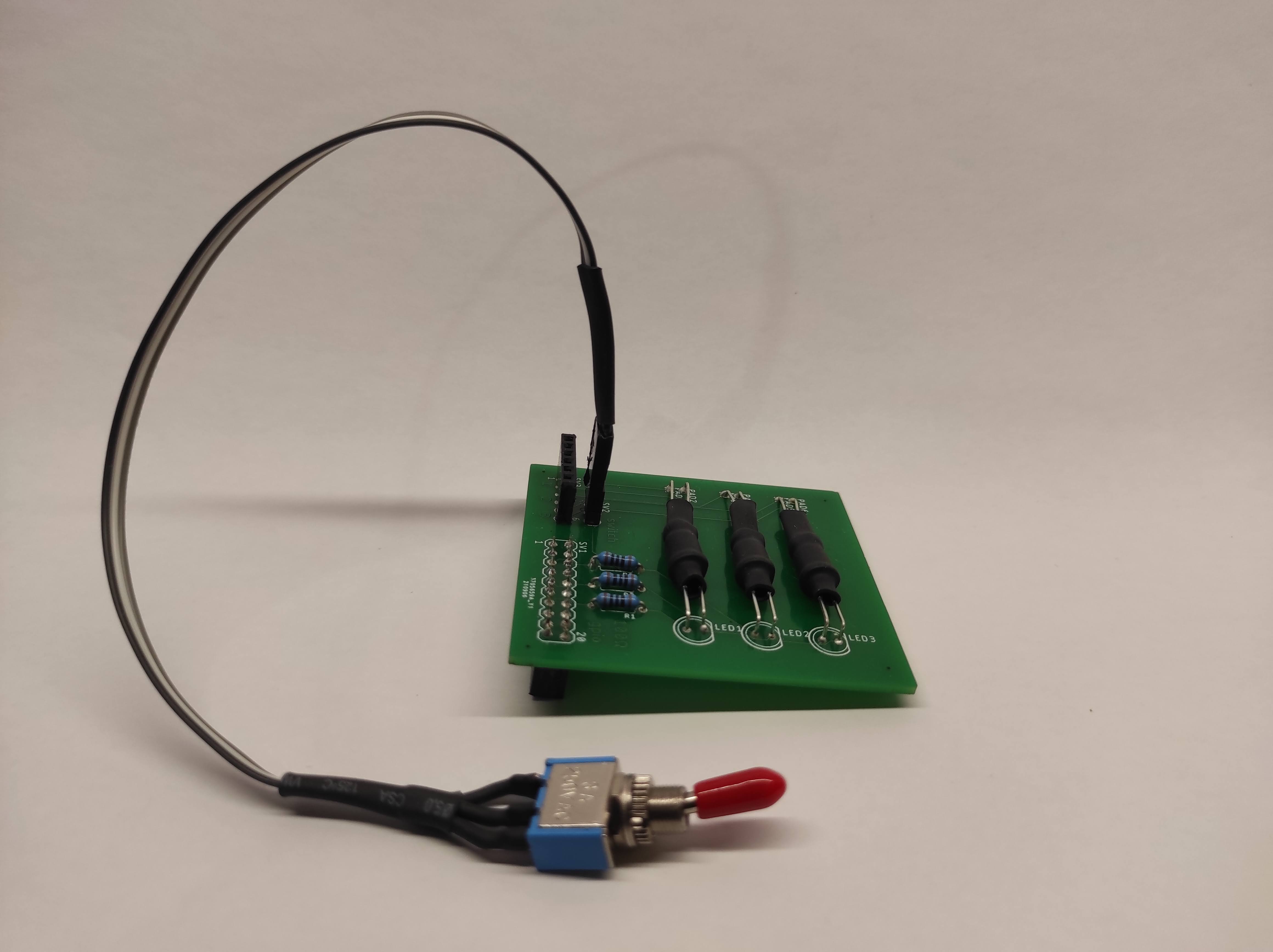
When you set it up, you can SSH to it (better way comming) and run a python script that asks you which one of the three devices.
you want to turn on (default,but you can modify it). Your choice turns on one of the LEDs that shines directly to a photoresistor.
The photoresistor lowers it's resistamce to minimum and shorts the circuit(tuns on the device),as if you pressed a button.
Parts you will need:
(All links mentioned here leads to czech sites,but by the model number you can find it elsewhere.)
3* Photoresistor (i use the LDR5516 ).
Switch or pinhead jumper
Female piheaders
-Crimping contants
KONPC-SPK-PI,you can buy in bulk,they are really cheap,if you mess up.
-Plastic shells for crimping contacts
KONPC-SPK-10,buy more of them,they are cheap and you are gona ruin a few by sniping it.
-Female 2.54mm pinhead row
BL240G-V8,0,buy more of them,they are cheap and you are gona ruin a few by sniping it.
Male piheaders
-Female pihead row (for switch and output )
S1G26C,buy more of them,they are cheap and you are gona ruin a few by sniping it.
3* 100Ω Resistors
3* Good old 5mm white LEDs(3V)
Connector/pihead - for output you can either use some kind of 6pin connector or just pinheads.
PCB
-You can either use a multi-purpouse PCB or a printed one.(Order one based on my schematics or just download the gerber .ZIP file from my
Github page.)
soldering equipment
-Soldering iron
-Tin(I recommend >1mm)
-Some good flux or a soldering paste
-Wet sponge for cleaning the soldering iron.
-Additional soldering eqpiment like: third arm,soldering iron stand,magnifying glass.....
Some generic cable
And obviosuly Raspberry Pi,theoreticly you can use any of the(except pico) but i reccomend one with a ethernet port.
If you have any feedback at all,comments,improvements,typos....
Please contact me at: piswitch.feedback@gmail.com .
And if you decided to make one,please send me picture of your creation,i would love to see it. Thanks! :D